MONITOR YOUR BACKUP GENERATOR
WITH
ARDUINO UNO
Like many home owners I have a backup generator. For a long time I have wanted to know how much power I am using from the generator and if the load is more or less balanced on the two legs. Recently I decided to tackle this issue.
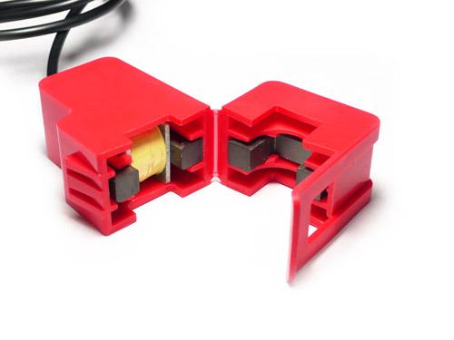
I wanted a solution that would be interesting and use an Arduino. A little research led me to an interesting little gadget... a split core sensor that provides an analog output of 1VAC for 30 amps AC. At less than $10 this seemed like a good choice.
Non-invasive AC current sensor
THE HARDWARE:
I bought a couple of these things and clamped one around each leg of the generator feed. They seemed to work very well. However, the Arduino could not read the 1 VAC for 30 amps output. The addition of a diode to the output provided a half wave rectified version of AC signal and the Arduino could read that. Unfortunately, the diode drop created a BIG dead band. The addition of an OP AMP before the diode would help, but there would still be a dead band on the low end. I could play with the gain to make the higher power come out more or less correct, but I could not see the lower power. Then I discovered the precision rectifier or “super diode”
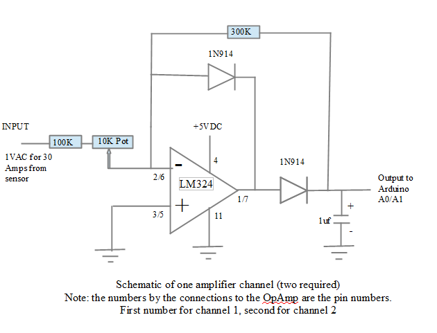
The “super diode” is an OP AMP trick to eliminate the diode drop and rectify an AC signal. An improvement on the “super diode” circuit makes it full wave instead of half wave. There are plenty of papers describing how this all works and I am not going to go into that here. What I will do is give you the circuit that I ended up with and tell you where to get all the parts.
The LM324 is a quad OP AMP in a 16 pin package. Two of the amplifiers channels are required, duplicating this circuit for each one. The 5VDC is provided by the Arduino. I built the circuit an Arduino project shield.
Originally I used a 3.2” TFT LCD display with touch screen and an Arduino MEGA 2560. I decided to rework it with the much less expensive UNO and a 16 character by 2 line display. The display is from Adafruit and they have a library to support it.
I assembled the project on a prototyping shield and checked it out. Be careful when you put the parts on the prototyping shield. Remember that it has to fit on the UNO and the display shield has to fit onto it.
Be sure to test your prototype shield circuit before stacking it on the UNO. The best way to do that is to connect the sensors to the circuit then separate the two wires of an extension cord and clamped one of the sensors around one wire (careful, don't cut the insulation). You will need to power up the circuit. This can be done by connecting the +5 and ground to a battery. It does not need to be +5, it can be a 6V or 9V battery. Check to see that the DC output at the pins that will to to the UNO A0 and A1 change as you change the current detected by the sensors. I used a an electric heater that would do 600, 900, and 1500 watts. The 10K pot is used to balance the two channels so that they read the same. The actual calibration is done by adjusting a constant in the Arduino code. It is not really important what voltage you get as long as it responds to the current seen by the sensors. That is, if you double the load current the voltage should double. If you remove the load (but keep the sensors connected to the circuit) you should see 0V.
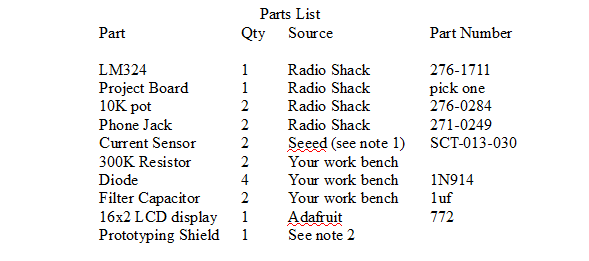
NOTE 1: http://www.seeedstudio.com/depot/noninvasive-ac-current-sensor-30a-max-p-519.html?cPath=144_154 or just search for SCT-013. Several US suppliers have it or you can get it from the manufacturer in China.
NOTE 2: be sure you gat a prototype shield that allows another shield to be stacked on it. Some do not or at least must be assembled with stacking headers.

Block Diagram of completed project
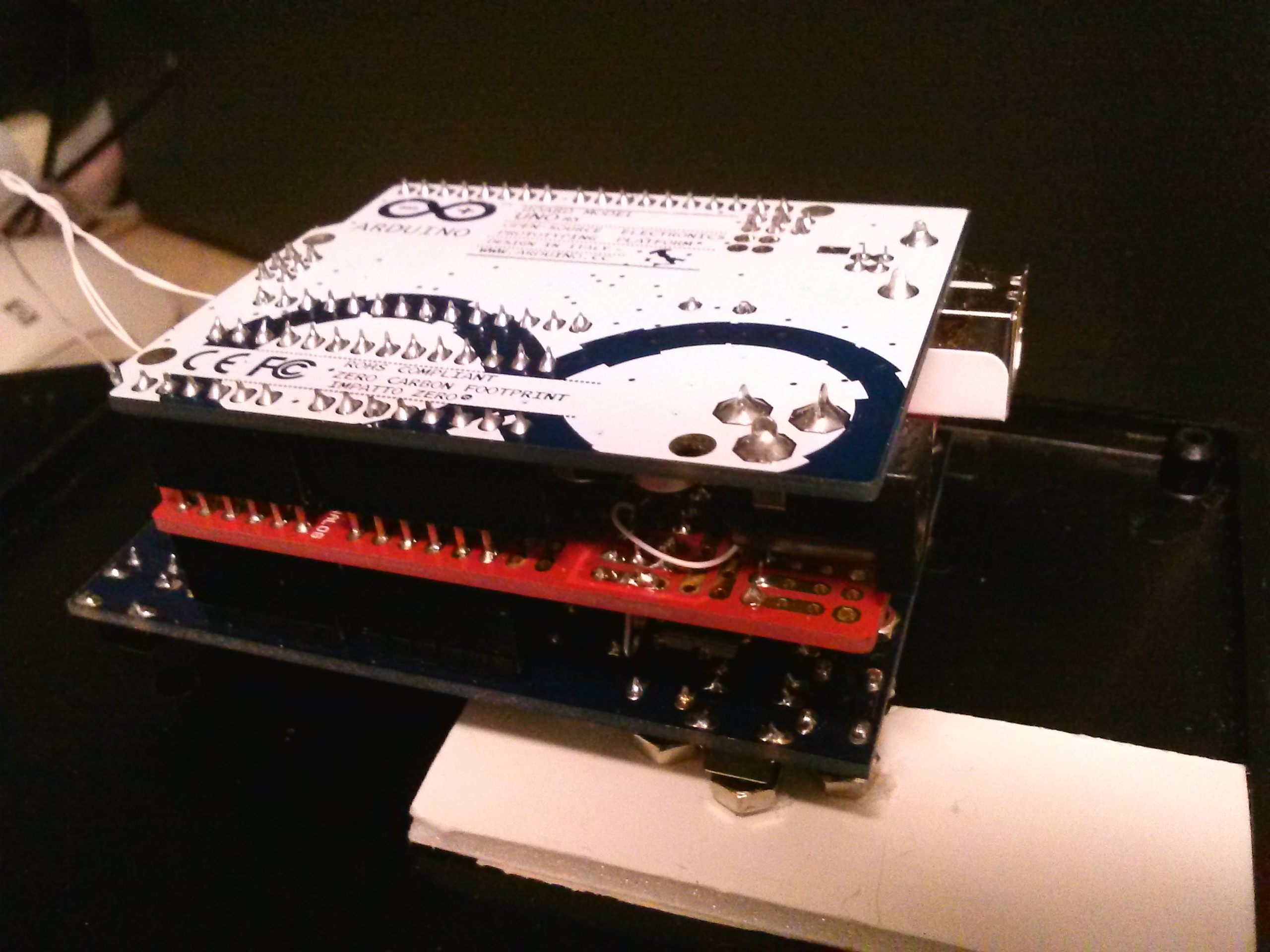
Here
is a picture of the completed project. It is upside down, with the
display screen facing the table. On the top is the Arduino UNO, under
that the prototyping shield, then the 16X2 display shield.
THE SOFTWARE:
To get a copy of the sketch point your browser to: http://firebottleradio.com/watts/watts-uno.ino
The source code will be displayed. Just save this to a directory named “watts-uno” in your Arduino sketch directory.
You will also need the display and touch screen library. Go to:
https://github.com/adafruit/Adafruit-RGB-LCD-Shield-Library
Everything else that the sketch uses is standard Arduino IDE stuff.
Look in the sketch for two lines:
sv=sv/0.212;
sv1=sv1/0.212;
At this writing they are lines 123 and 124. This is the conversion from the value read from the A/D converter to watts. I have made a couple of these things and have not needed to adjust these lines. However, if you don't get the right answer adjust it here. One warning, the digital value that the Arduino reports is a function of the supply voltage to the Arduino. If you test all of this with the USB cable powering the Arduino then switch to a power supply into the coaxial connector you will probably get a different calibration. Just compute the error and make an adjustment to these numbers. I found that 0.212 worked fine with the power supply and gave answers that were high with the USB. Your mileage may vary.
If you don't like my code style, too bad. I know that too many variables are global. At one point I was having trouble with the Arduino and thought it was caused by heap fragmentation and moved all the variables to global. Turns out that was not the problem and I just never put them back where they belong. Also, the sketch was adapted from another sketch done for another application and the code suffered a little in the conversion.
Here is what the display looks like :
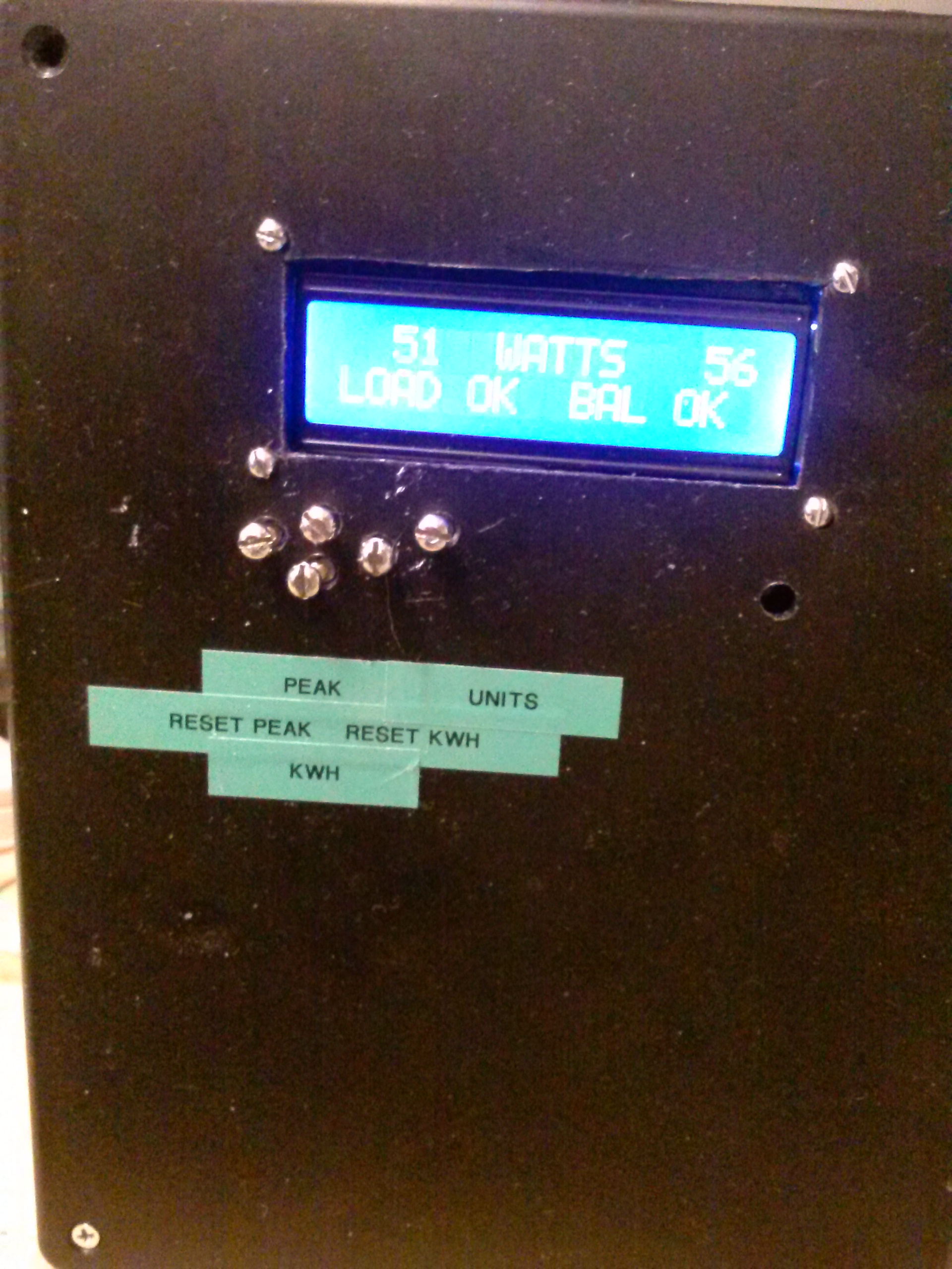
The load on each leg (in watts) is displayed. The “LOAD OK” indicates that neither leg is over loaded and the “BAL OK” indicates that the load on the two legs is balanced (within an adjustable limit). Pressing PEAK button will display the highest load seen since pressing the RESET PEAK button. Pressing KWH button will display the kilowatt hour total since a RESET KWH. If the load is not balanced (in my setup within 1000 watts) then the display will indicate “BALANCE”. The UNITS button will change the display to AMPS instead of WATTS. You will notice that I cobbled together small bolts to extend the buttons on the display through the front of the box. When you order the display and shield from Adafruit I recommend that you order a set of switches that have the LONG buttons. That makes my cobble unnecessary.