HO DEAD RAIL
WIRELESS REMOTE CONTROL
This document describes my project to make a HO model train control that is wireless, dead rail, and a reasonable cost.
My goal was to make a system that would cost less than $60 for the control head to control 5 trains and
that the cost to convert each locomotive would be less than $15, not including the battery.
The battery should cost less than $20.
The system must be wireless and the control head must be battery powered with a battery life of
at least 3 hours continuous operation.
I am not a model railroad hobbyist.
I am a retired software engineer and my hobby is making things with microprocessors.
I saw a YOUTUBE video about refurbishing a layout and decided that an interesting project
would be a system that would use microprocessors to control HO trains wirelessly.
After a couple of weeks of design and coding I have a working system
that consists of a control panel about the size of a cell phone
and a microprocessor and motor controller for each locomotive.
At this time I use a NiMH 9.6 volt battery in a car behind the locomotive,
but it could be done with 12 volts DC on the rails and no battery required.
OVERVIEW
Locomotive Motor Control
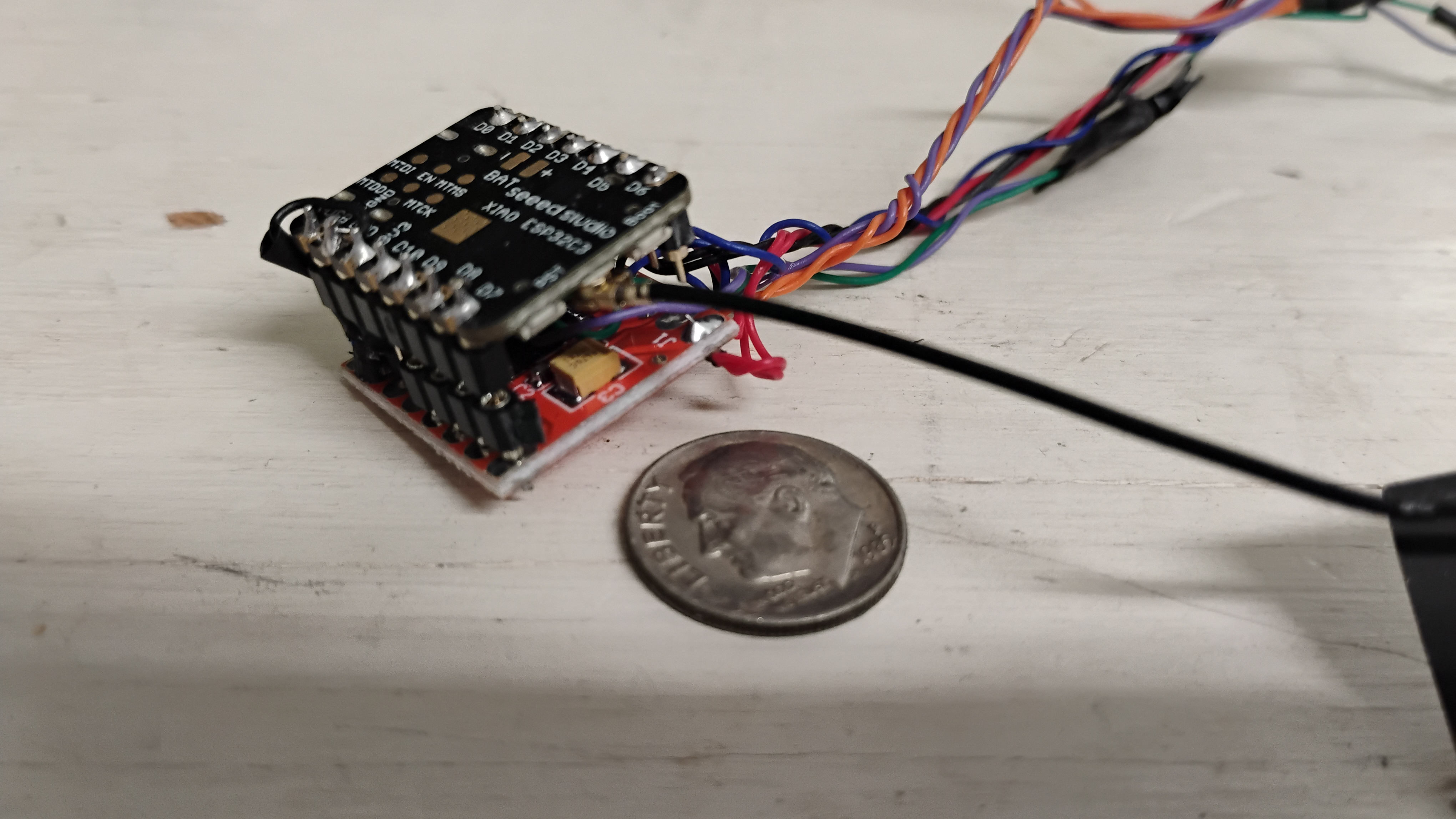
The motor control in the locomotive is a SEEED ESP32C3.
The SEEEDC3 is a single core 160mHz processor.
This processor board is about the size of a postage stamp and costs about
$9.00 from Amazon or a little less if bought three at a time (about $20 for three).
In addition to the microprocessor a motor controller is required.
This device is a TB6612FNG dual MOSFET H bridge controller
available from Amazon for about $9.00 for four.
The motor controller works by taking a pulse width modified (PWM) signal
and a direction signal from the microprocessor and sends it to the locomotive.
The voltage supplied to the locomotive is always full battery voltage
and the speed is controlled by varying the pulse width.
I use a 9.6 volt NiMH battery.
This battery is easier (and safer) than LiPO and fully charged it is a little over 11 volts.
The motor controller is limited to 12 volts.
Stacked together these parts make a neat package
(about 24mm X 24mm X 10mm) that will fit into almost any locomotive.
I have retrofitted 5 or 6 locomotives (junkers that I bought on eBay and repaired).
One had so little space that I separated the two parts by small wires
and placed them in different parts of the shell.
It is also possible to put the microprocessor in the battery car,
but I have not yet found this necessary.
Display and control head
The control uses an ELECROW 5” display with ESP32S3 processor.
This board includes touch control.
It sells for about $50 on AMAZON and is currently on sale for $21 (plus shipping and customs) directly from Elecrow.
It is powered by a 2000 mAh LiPo battery.
This battery increases the cost of the control head by about $11.
My software provides the capability to control six trains.
Various functions are provided that I will describe later.
The display/control head talks to the individual locomotive speed control
microprocessors by ESP NOW protocol.
This is a very light and fast wireless protocol that DOES NOT require a WiFi access point.
It allows the control head and the individual motor controllers
to communicate quickly and error free.
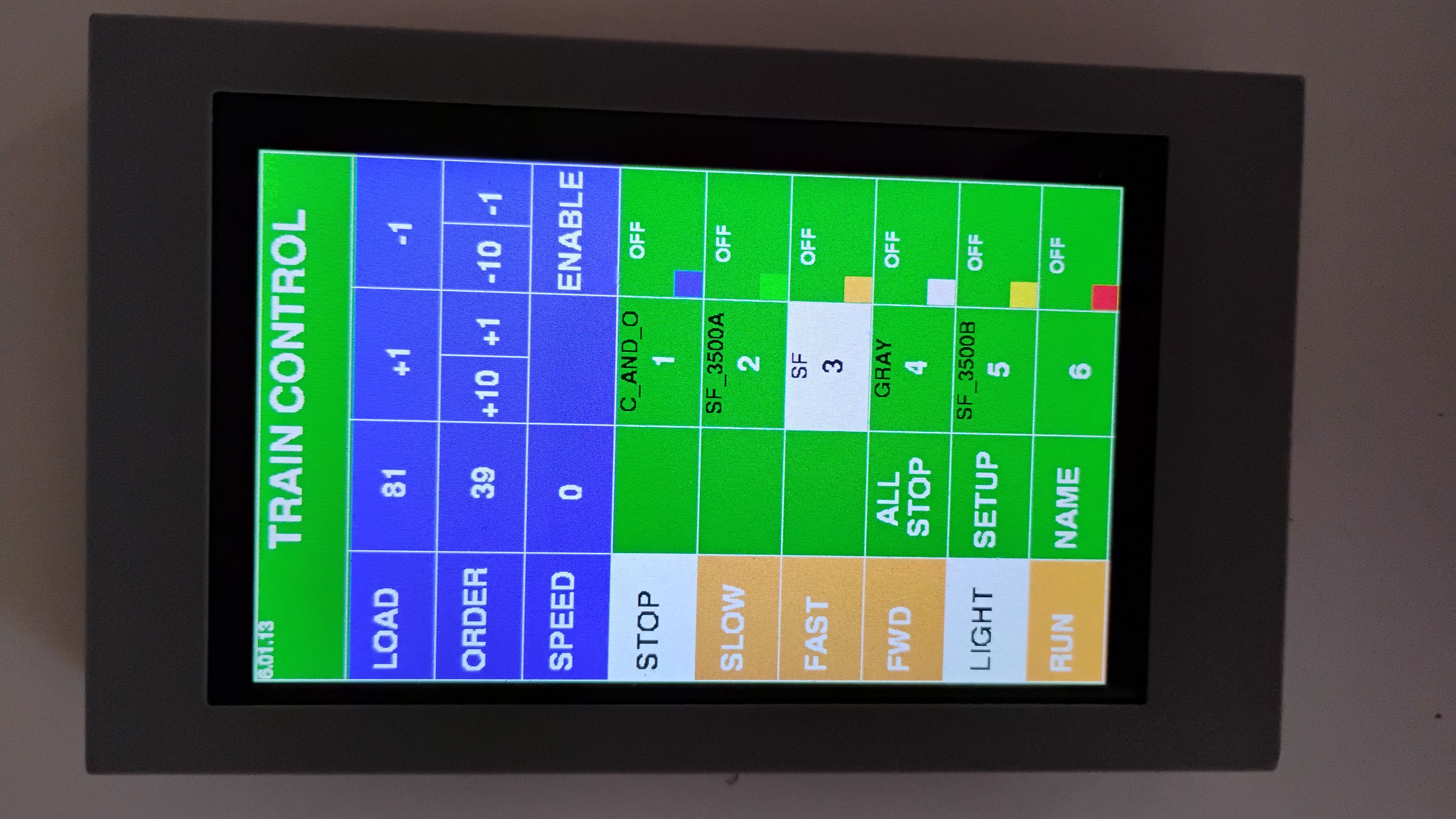
Upper left: software version, currently6.01.13
Upper right: Battery voltage.
Across the top, below the “TRAIN CONTROL” label in the BLUE area:
LOAD: (1-100) simulates a heavy or light train load.
Low numbers cause speed changes to take place quickly.
Large numbers cause speed changes to take place slowly. +1 to increase, -1 to decrease.
ORDER: (0-200) the final speed after the train accelerates. Press +10 or +1 to increase, -10 or -1 to decrease
SPEED: the current speed (0-200)
SPEED: the current speed (0-200) This is display only. It is the current order being sent to the train.
Along the left side in the ORANGE area:
STOP: immediately stop the motor.
SLOW: gradually reduce speed until 0.
FAST: gradually increase the motor speed
FWD/BKWD: locomotive direction (pressing this will change the direction and immediately stop the motor).
RUN must be pressed to start it again
LIGHT: turns the headlight on/off
RUN: Start the locomotive moving initially at 0 speed
gradually increasing up to the ORDER.
The rate of change depends upon the LOAD command.
NOTE: the following three selections should be in the ORANGE area.
I will fix this in the next revision.
ALL STOP: Immediately STOPS all trains.
SETUP: open the SETUP PAGE to configure the train.
NAME: add a name to the statue.
In the GREEN area on the right side:
The right column shows the status of the six locomotives.
OFF if disabled, RUN if it is running, STOPPED if it is stopped.
If the battery is low a message will be shown.
The left column shows the 6 trains that can be controlled.
The selected train has a white background.
Above the train number is the name (up to 10 characters) that can be set by pressing NAME page.
The train number GREEN if the control has established a connection to the motor control processor in the locomotive.
RED if it is NOT connected.
The selected train can be enabled or disabled by pressing ENABLE/DISABLE in the blue area.
SETUP PAGE
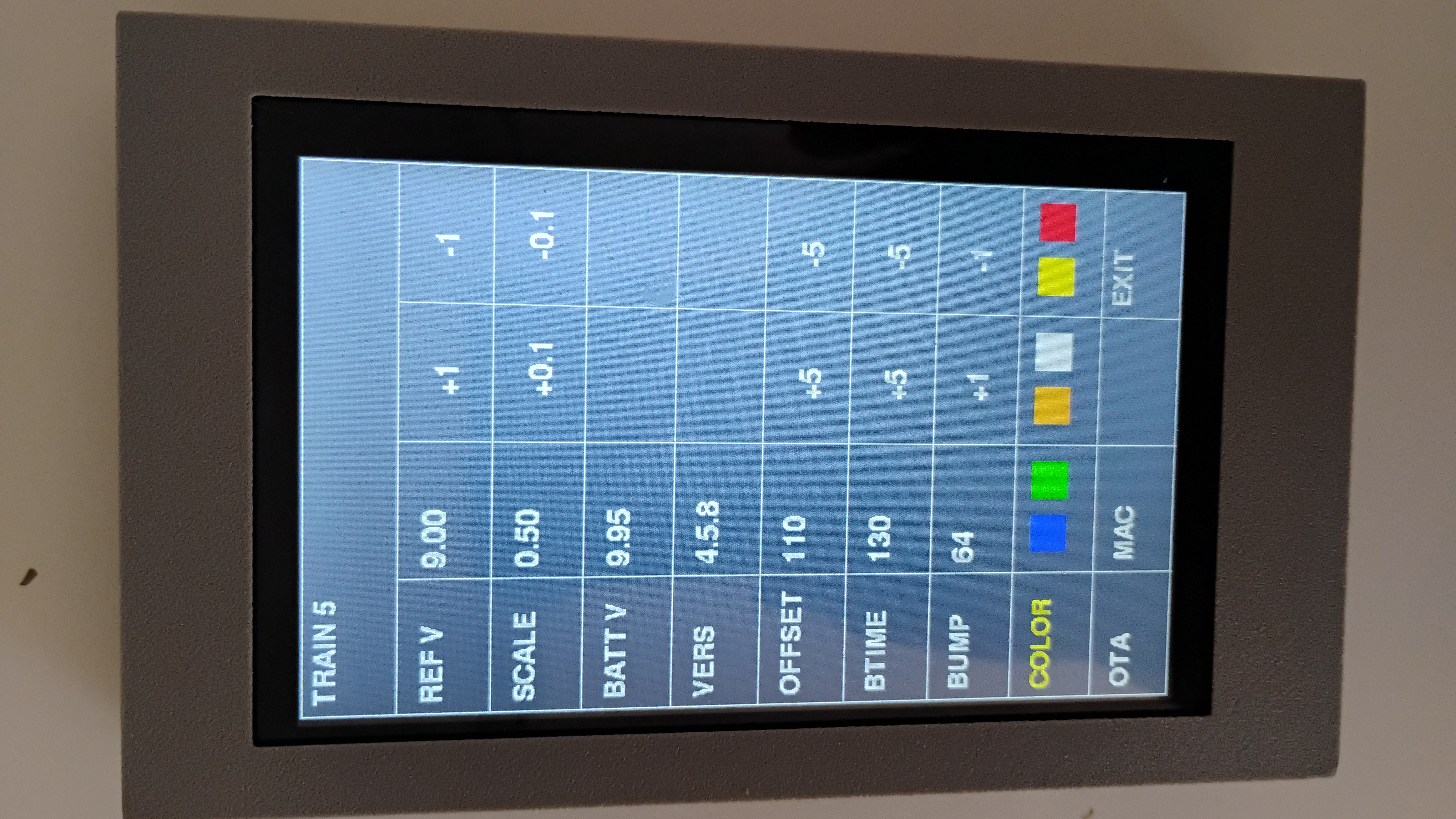
The SETUP button enables a page that allows the individual locomotives to be configured.
The actual control range of the motor controller is 0 to 100% pulse width.
However, below some level will not actually make the motor run.
This point is specific to the locomotive and the setup page allows configuration of this point.
In addition, the small DC motors tend to stick when stopped and a little bump is required to get them going.
The setup page configures the amount and duration of the bump.
I also implemented an algorithm that reduces the speed order when the battery is fully
charged and increases it when the battery is nearing full discharge.
This attempts to keep the locomotive response somewhat the same as the battery discharges.
The OTA button enables Over The Air update of the software.
Normally this is done with a USB cable, but when the processor is embedded in the locomotive this is difficult.
It is possible to update over WiFi, but that is not available when the ESP NOW protocol is in use.
Pressing OTA orders the locomotive processor to reboot in OTA over
WiFi access point mode and then reboot in ESP NOW mode after an update is done.
The MAC button opens the MAC address page. Communication with ESP-NOW
requires that the control and the locomotive processors know each others
MAC address (NOT the IP ADDRESS).
Normally, you would have to run software
that discovers the MAC addresses and then enter them into the CONTROL head and
motor control processors. I implemented a procedure that automatically
discovers the control head and motor control MAC addresses.
The discovered MAC must be entered in the MAC list on the MAC page
so that the control head will know which train number is which. When
the control head find a motor controller with an “unregistered” MAC
the address is displayed. Just open the MAC page and click on the
train number that should be associated with the discovered MAC.
All settings in the main page, setup page, and name page are saved and restored when the control head is turned on.
Where is this going?
As I said, I am not a railroad hobbyist. I write software and design systems.
If anyone wants to take the software and build a system I will give you the source.
It is coded in C++ using the Arduino IDE environment.
I am fond of the old IDE version (1.18.9 I think) but it will work just as well using the latest 2.x version.
The ESP32 core is the latest from Espressif (3.2 I think).
If you want to give it a try, but don’t want to get into recompiling the source code
I would consider programming a display board/battery and 6 locomotive processors with motor controllers for you.
You would have to build everything. However, that is relatively easy.
There are only 5 connections between the processor and the motor controller plus ground and +5.
I have a schematic.
If someone wants this service, contact me and we can sort out the cost.
If you do everything yourself the total cost to make a control head and 6 motor control processors should be under $100.
If you are interested in any of this, contact me at:
sam@firebottleradio.com