Home Internet of Things
ESP8266 Building Block #1
Refrigerator Monitor
This is the first in a series of ESP8266 hardware/firmware projects. These projects are not just stand alone projects, but will be linked together in an extensive home Internet of Things network. At this time the entire system is working, but initially the project write up will just be the stand alone version. Later separate projects will revise the firmware to integrate them into the whole system. No changes are required to the project hardware to do the integration, just revised firmware. After you build this (relatively simple) first block go on to Building Block #2 and we will extensively revise the firmware, build another (even simpler) ESP8266 board and get serious about IoT stuff.
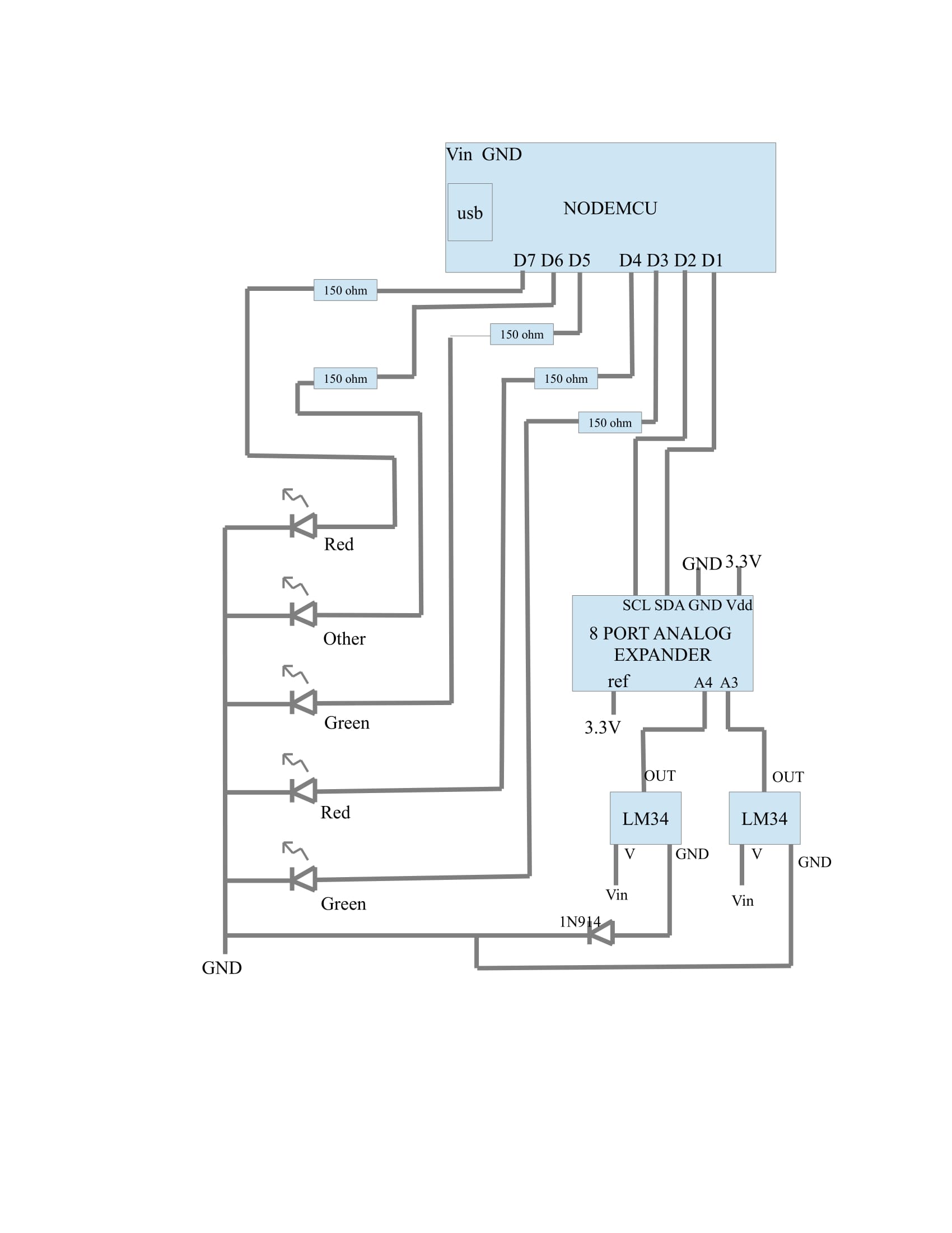
The hardware for this first project is relatively simple. It consists of a NODEMCU type ESP8266 break out board. These are available from dozens of suppliers. You will also need:
The Arduino IDE (https://www.arduino.cc/en/Main/Software) plus the ESP8266 board support plug-in. I am not going to tell you how to get the IDE and the EXP8266 board plug-in going. There are several very good write ups on this and there no point in adding another one.
ESP8266 analog input expander (version 2) made by AllAboutEE but sold by tindie.com.
Two LM34 Fahrenheit temperature sensors (available from DigiKey).
One 1N914 diode (again, from DigiKey).
Five 200 ohm (or so) quarter watt resistors and five LEDS. I recommend two green, two red, and one some other color. These are available from any number of sources. I had them in stock, but I am sure DigiKey will have them.
You will also want a piece of about 1.5” by 2” perfboard. The size does not matter much except that it needs to be large enough for the NODEMCU board and leave room for the resistors , LEDs, the 1N914 and a place to connect the LM34 wires (more about this later).
I always use female pin headers to make a socket for the NODEMCU. That way I can recover the processor if I abandon the project. Generally I put in enough of the female pin headers to be able to insert resistors (2 holes each) and LEDs (2 holes each) and the 1N914 (2 holes). The LM34's take three wires each but they want to be long enough to place the board on the top of the refrigerator and route the wired through the door seals into the fresh and frozen compartments. By the way, I use 30 AWG wire wrap wire for the wires to the LM34. This is VERY fine wire and won't make the door seal leak air. You don't want to make the wires to the LM34s more than about 25-30 inches. Longer than that and the temperature reading will be unstable and incorrect. This can be fixed, but we are not going to go into that here. I am not going to hold you hand to build the hardware. This is a relatively simple project and you should be able to figure it out. If it seems to be beyond your skills then start with a really simple project and work up to this.
You will also need the sketch for this project. You can get it at:
http://firebottleradio.com/iot/block1.ino
OK, if you are wondering why there is a diode in the ground lead of one of the LM34 temperature sensors I will explain. This sensor goes into the freezer compartment. The LM34 provides 10mv/deg F with a base of 0 Deg F. Since the freezer goes to negative F temperatures this will not work. The LM34 is capable of handling this, but it needs a negative voltage in place of ground on the third pin. An easy way to take care of this is to add the 1N914. This will provide a reference at the third pin that is about 0.48 V offset. This works, but it introduces a 480mv (48 Deg F) offset in the output temperature. This is easily corrected in the firmware. You may wonder why the offset is 0.48V not closer to 0.6V. Because the LM34 draws so little current the diode is not in its linear region. You could fix this with a resistor, but since the current never changes the fact that it is non-linear is unimportant.
I have connected the V supply for the LM34 to the Vin. If you power the NODEMCU from the USB this will be 5V. If you power it from an external power supply I recommend that you use 5V. You could power the LM34 from 3.3V from the NODEMCU and it seems to work. However, the LM34 is supposed to have at least 5V. Please note that a few NODEMCU boards do not work this way. When powered by USB the 5V is available on the pin just above SD3. When powered from Vin there is no voltage at this pin. This makes it a little difficult to seamlessly switch from power supply to USB powered. I just try to avoid these break out boards. The odd ones that I have are all the type that is wider than the “standard” NODEMCU. If you stick to the narrower boards you should not have a problem.
Build it all up and check for proper connections then fire it up. At room temperature the two RED LEDs will light. Don't worry if this does not happen immediately. The temperatures are highly filtered and also the temperature has to be out of spec for 60 seconds before the LEDs are illuminated. Put the LM34 connected to the 1N914 into the freezer compartment and the other one in the fresh food compartment. After 30 minutes or so it should stabilize and have two GREEN leds. If you plug in a USB cable and fire up the serial monitor in the Arduino IDE you will see the raw and filtered temperatures.
This is building block #1 of ??? (we will see). If you have more than one refrigerator build a second one and we will use both of these in building block #2. This block will collect the temperatures from two or more of the block #1 devices and send text messages to you smart phone if the refrigerators are too warm.
If you have a freezer then you don't need two sensors and the analog pin on the NODEMCU is sufficient. Just remove all reference to the A/D converter from the sketch and change the converter.read() calls to analogRead(A0). You will also want to remove everything about reading and filtering the fresh food temperature.
After you have this working move on to the block #2 project. It is actually much easier hardware, but the firmware starts to get more complicated (but much more interesting).
To go on to the next building block click here: http://firebottleradio.com/iot/block1a.html